Soil resistivity testing is a key input for safe and compliant earthing design. GridServe provides Wenner method soil resistivity testing and earthing design reporting for solar, BESS, EV charging, commercial developments and utility connection projects across Victoria.
Our reports are prepared for use in DNSP connection applications and earthing studies, including projects connected to AusNet, Powercor and CitiPower networks.
Who This Service Is For
Target Customers and Applications
• Solar farm and BESS connection applications
• EV charging infrastructure projects
• Commercial and industrial developments
• Kiosk substation and HV customer connection projects
• Earthing design, EPR and step and touch voltage assessments
• DNSP information requests requiring site-specific soil data
01 — Why It Matters
Why Soil Resistivity Matters
Soil resistivity, measured in ohm-metres (Ω·m), describes how strongly a given volume of earth opposes the flow of electrical current. It is the primary input parameter for the design of earthing systems for power infrastructure.
In the context of utility connections — including solar PV arrays, battery energy storage systems, EV charging infrastructure and grid-tied commercial installations — an earthing system designed without measured soil data can result in dangerous touch and step potentials during fault conditions, equipment damage, and non-compliance with DNSP requirements.
Design reference: Soil resistivity testing supports earthing design work carried out with reference to AS/NZS 3000, AS 2067, IEEE Std 80 and DNSP connection requirements. |
Soil resistivity varies significantly depending on soil type, moisture content, temperature, mineral composition and depth. Sandy soils can exceed 1,000 Ω·m, while moist clay may be as low as 20 Ω·m. This variation means generic assumed values can result in either over-engineered or inadequately designed earthing systems.
02 — Test Method
How the Wenner Method Works
The Wenner method uses four equally spaced test electrodes to measure how the soil responds to injected current. By repeating the test at increasing electrode spacings, we estimate how soil resistivity changes with depth. This data is then used to develop an earthing design model for earth grids, EPR, step voltage and touch voltage assessments.
Principle of Operation
A known alternating current is injected between the two outer electrodes (C1 and C2), and the resulting voltage drop is measured between the two inner electrodes (P1 and P2). Applying the Wenner formula gives the apparent soil resistivity at a depth approximately equal to the electrode spacing.
WENNER FORMULA — APPARENT SOIL RESISTIVITY ρ = 2π · a · R ρ = apparent soil resistivity (Ω·m) a = electrode spacing (m) R = measured resistance (Ω) |
Depth Profiling
Electrode spacing is progressively increased — at 2 m, 4 m, 6 m, 16 m, 32 m, and 64 m — with a resistance measurement recorded at each interval. This sequence efficiently samples shallow, intermediate and deep strata in a single traverse, building a complete subsurface resistivity profile used directly in earthing system design.
03 — Equipment & Field Method
Field Testing Equipment and Method
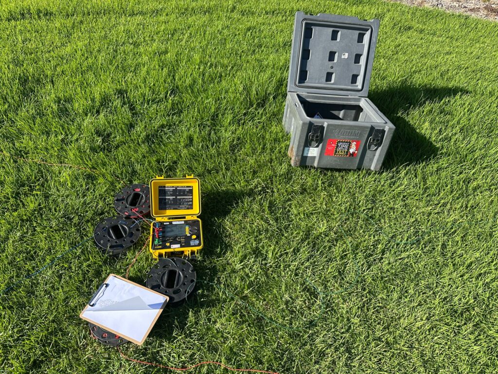
GridServe uses the AEMC Model 6471 Ground Resistance Tester for all soil resistivity surveys. This instrument is purpose-built for the four-electrode Wenner method for soil resistivity testing. Earth resistance testing can also be completed where required.
INSTRUMENT AEMC Model 6471 — Ground Resistance & Soil Resistivity Tester | |
Test method | Four-electrode Wenner method |
Resistance range | 0.001 Ω – 20 kΩ |
Test frequency | 94 Hz / 105 Hz (AC) |
Accuracy | ±2% of reading |
Protection rating | IP54 |
Standards | IEEE Std 81, ASTM G57 |
The AEMC 6471 applies an AC test signal and measures the resulting voltage, computing resistance directly. Its use of alternating current at specific test frequencies eliminates DC polarisation effects and rejects mains frequency interference — a critical requirement when testing near energised infrastructure.
Field Procedure
1. Site assessment and survey line selection
The test area is inspected and a straight traverse selected, oriented to avoid underground services and existing earthing electrodes. Underground asset plans (Dial Before You Dig) are reviewed prior to electrode insertion.
2. Electrode placement
Four stainless steel spike electrodes are driven into the ground at equal spacings, placed in a straight line and measured with a tape. Spacing is recorded on the field data sheet.
3. Connection of the AEMC 6471
The instrument’s four terminals are connected via colour-coded cable reels: C1 and C2 (current injection) to outer electrodes, P1 and P2 (voltage sensing) to inner electrodes.
4. Resistance measurement and recording
The instrument applies the test signal and displays the resistance R in ohms. Multiple readings are taken at each spacing to confirm repeatability, and all values are recorded on the field data sheet.
5. Spacing increments and profile building
Electrode spacing is increased at 2 m, 4 m, 6 m, 16 m, 32 m and 64 m, building a depth profile of apparent soil resistivity across the full depth range of interest.
6. Calculation and reporting
Apparent soil resistivity (ρ = 2π × a × R) is calculated for each spacing, tabulated and plotted. Results are incorporated into a formal report and used to design the earthing system.
04 — Deliverables
What You Receive
✓ Site soil resistivity testing using the Wenner four-electrode method
✓ Raw field readings and calculated apparent resistivity at all electrode spacings
✓ Soil resistivity profile and interpreted soil model
✓ Test location details and field conditions
✓ Earthing design inputs suitable for engineering studies
✓ Practical recommendations for earthing design
✓ Technical report suitable for project records and DNSP submission support
✓ Optional input into AS 2067 / IEEE 80 style earthing studies
05 — Reference Data
Typical Soil Resistivity Values
The following indicative values represent common soil types encountered across Victoria. Actual site measurements vary significantly, which is precisely why field measurement is essential.
Soil / Material Type | Resistivity Range (Ω·m) | Earthing Difficulty |
Wet clay / marshy ground | 10 – 40 | Low |
Loam / agricultural soil (moist) | 20 – 100 | Low |
Clay / silt (moderate moisture) | 50 – 200 | Moderate |
Sandy clay | 100 – 500 | Moderate |
Sand (dry) | 500 – 2,000 | High |
Gravel / coarse aggregate | 1,000 – 5,000 | High |
Rock / granite | 5,000 – 100,000+ | Very High |
High-resistivity soils require more complex earthing solutions such as deep driven rods, horizontal ring electrodes, soil treatment with bentonite or conductive backfill, or a combination of approaches. GridServe’s survey data directly informs which solution is technically appropriate and cost-effective for each site.
06 — Standards & DNSP Alignment
Standards and DNSP Alignment
Soil resistivity testing supports earthing design work carried out with reference to AS/NZS 3000, AS 2067, IEEE Std 80 and DNSP connection requirements.
Our reports are prepared for submission support as part of Powercor, CitiPower and AusNet connection application processes.
Relevant: soil resistivity testing Victoria · Wenner method soil test · earthing design report · DNSP connection earthing study · Powercor soil resistivity testing · AusNet earthing report · BESS earthing study · solar farm earthing design · EV charging earthing design. |
07 — Why GridServe
Why Use GridServe
• Field testing carried out by qualified electrical engineering personnel and competent technicians
• Calibrated and traceable test equipment
• Reports structured for engineering review and DNSP submission support
• Clear assumptions, raw field data and practical design recommendations
• Capability to support follow-on earthing design, EPR, step voltage and touch voltage studies
Need soil resistivity testing for your project? Send us your site address, DNSP, project type and required submission date. GridServe can confirm the test scope, access requirements and reporting timeframe. → Email: anilc@gridserve.com.au → Phone: 1300 170 852 |
Written by
Anil Chaudhary
<div class="elementor-element elementor-element-0c15f3f elementor-widget elementor-widget-text-editor" data-id="0c15f3f" data-element_type="widget" data-e-type="widget" data-widget_type="text-editor.default"> <p class="team-bio">Anil Chaudhary is an experienced electrical engineer and energy infrastructure professional with extensive expertise in power systems, renewable energy, and battery energy storage systems. He combines strong technical capability with strategic leadership, having worked with major Australian utilities and infrastructure organisations across the design, engineering, and delivery of critical energy and telecommunications projects.</p><p class="team-bio">Anil has held senior leadership roles including General Manager at RSS CommTel, leading major infrastructure programs and operational teams. At GridServe, he leads engineering strategy, project delivery, and client partnerships.</p><div class="team-section-label">Key expertise</div><ul class="expertise-list"><li>Battery Energy Storage Systems (BESS)</li><li>Solar PV integration</li><li>Power system studies</li><li>Earthing system design</li><li>Lightning protection design</li><li>Grid compliance assessments</li><li>Engineering strategy & project delivery</li></ul> </div><h3 class="elementor-heading-title elementor-size-default">Past organisations </h3><div class="bio-bottom-list elementor-element elementor-element-d87ceed elementor-icon-list--layout-inline elementor-list-item-link-full_width elementor-widget elementor-widget-icon-list" data-id="d87ceed" data-element_type="widget" data-e-type="widget" data-widget_type="icon-list.default"> <ul class="elementor-icon-list-items elementor-inline-items"> <li class="elementor-icon-list-item elementor-inline-item"> <span class="elementor-icon-list-text">Power & Water Corporation</span> </li> <li class="elementor-icon-list-item elementor-inline-item"> <span class="elementor-icon-list-text">AusNet Services</span> </li> <li class="elementor-icon-list-item elementor-inline-item"> <span class="elementor-icon-list-text">Ausgrid</span> </li> <li class="elementor-icon-list-item elementor-inline-item"> <span class="elementor-icon-list-text">Telstra</span> </li> <li class="elementor-icon-list-item elementor-inline-item"> <span class="elementor-icon-list-text">RSS CommTel</span> </li> </ul> </div>
View all articles by Anil Chaudhary →